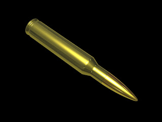
But this tutorial is only a modeling one and I will not cover rendering techniques. If you get stuck on the way make sure that you check the images under each step as they can help you to understand better what's going on . So let's get started:
First of all we need a reference image which you can download by clicking on the thumbnail below:

Step 1: Open 3Ds MAX go to the Create Panel - Standard Primitives and create a Plane in the front viewport:
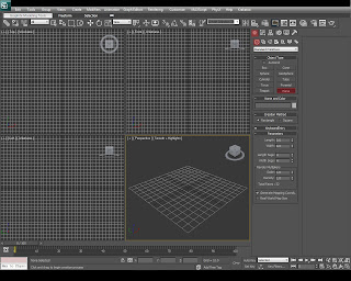
Step 2: Select the plane, go to the Modify tab and change its length to 910 and its width to 175. We must add these values because the reference photo that I've prepared for this tutorial is 175x910 pixels.
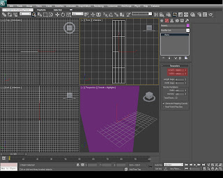
Step 3: Press M on your keyboard to bring up Material Editor, then in a Standard Material click on the diffuse box and pick Bitmap from the list.
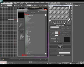
Step 4: A browse dialog will pop-up asking you for an image. Browse the Bullet Reference.jpg and then Open it.
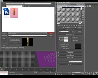
Step 5: Now we're back into the Material Editor, make sure that your Plane01 is selected, then press Assign Material to Selection button.
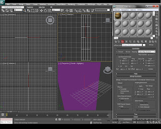
Step 6: Now press Show Standard Map in Viewport button in order too see the reference image inside 3Ds MAX's viewports (if your still can't see the image we assigned to the plane in the front viewport you need to press F3 to switch to shaded view).
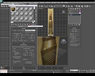
Step 7: Right click on the plane in any viewport and select Object Properties. In the Object Properties dialog disable Show Frozen in Gray and hit OK.
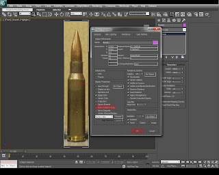
Step 8: Now press right click again on the plane in the viewport and select Freeze Selection. (we must do this so that we don't accidentally move the plane while we're creating the 3D bullet).
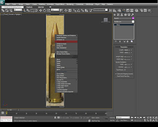
Step 9: Go to the Create Panel - Shapes - Line and before dragging the lines into the viewport make sure that you change the Initial Type to Corner and the Drag Type to Smooth (if you press click once in the viewport you'll create a corner vertex, if you choose to drag after clicking you will create a smooth vertex).
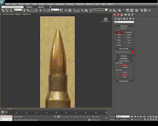
Step 10: Now starting from the top of the bullet go ahead and create a continuous line which should look very similar with the image below (as you can see we only create a half of the bullet because we will choose a modifier to obtain the actual geometry)
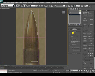
Step 11: After you've finished the line, select it and go to the Modify Tab then pick Lathe from the list.
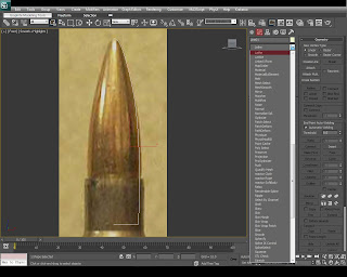
Step 12: Inside our Lathe modifier you will probably see that the geometry is not displaying correctly. Go ahead and press on the Min button under Align, now your line should align properly to create the actual bullet (if your bullet is black then try to enable Flip Normals to fix this issue) - and make sure that you check Weld Core's case too. Your result must look very similar with the image below.
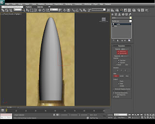
Step 13: With the line selected go into the Modify tab, pick the Line from the list and press on the show end result button. Now select your vertices and make adjustments to your bullet - because we have enabled show end result you will see the changes of the bullet in real time. Make adjustments to your line now to make the geometry look smooth and to match the reference image as closely as possible.
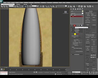
Step 14: Now using another line (Create Panel - Shapes - Line) create the bullet shell outline starting from the top to the bottom (only press clicks as we want to place only corner vertices).
If you can't create it into a single shot don't worry because you can edit it later (after you placed all the vertices go to Modify tab - Vertices and move them as you want).
Make sure you see the image below for a better understanding.
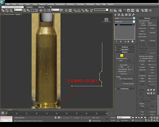
Step 15: With the bullet shell spline selected go to Modify tab - and select Lathe from the list to turn it into a geometry. Make the adjustments like you previously did for the bullet - check the image below.
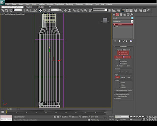
Step 16: Make adjustments to your bullet shell (spline) because later on you won't be able to do this anymore. After you've finished adjusting vertices, make sure that your bullet shell is selected, go to the Modifer tab and add an Edit Poly from the list on top. Inside Edit Poly select Edges (nr. 1 in the picture below) then with your Selection Tool (hotkey Q) pick all the horizontal edges of the geometry (you only need to pick one segment and then press Loop). After your edges are selected (8 in total in my picture) press on Chamfer Settings.
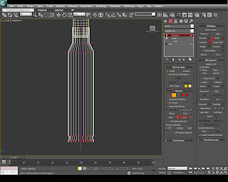
Step 17: Use a chamfer amount of 1.3 and hit OK. You'll see that every horizontal line that you selected had duplicated (we must do this so that we can smooth the geometry later on)
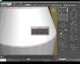
Step 18: Select the vertical edges as shown in the image and press on the Connect settings.
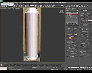
Step 19: Inside Connect Edges Settings change the Segments to 2 and the pinch value to 97.
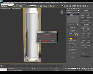
Step 20: After you connected the edges make sure that you select the vertical edges again (between the edges that you previously connected) and go to Connect Settings again but this time choose 2 Segments and 0 Pinch and 0 Slide.
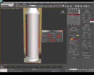
Step 21: Go to the bottom area of your bullet shell, go to the polygons selection inside Edit Poly, thick Ignore Backfacing and select all the polygons which form the bottom side. (make sure that you don't select anything else)
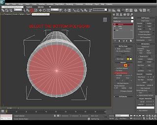
Step 22: With the bottom polygons selected like in the image below go to the Inset Options and use an Inner Amount of 1.3. Hit Apply.
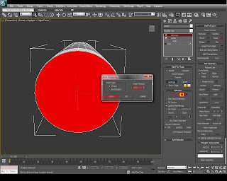
Step 23:Now change the value of the inset to 22.7 and press Apply again.
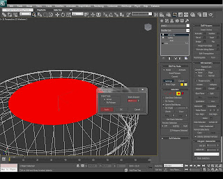
Step 24: Change the Inset Ammount to 1.3 and press OK.
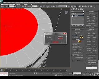
Step 25: With the polygons still selected go to Extrude Settings, change the Extrusion Heigth to -1.3 and click Apply.
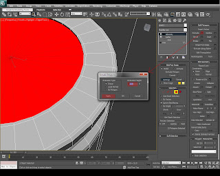
Step 26: Change the Extrusion Height to -4.4 and hit Apply.
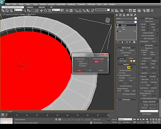
Step 27: One more time change the value of the Extrusion Height to -1.3 and finally click OK.
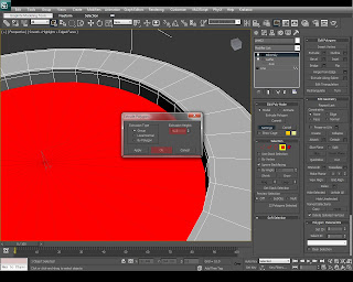
Step 28: Now we finished modeling the bullet shell but we need to apply a Chamfer Cylinder inside the hole that we've just created. Go to Create Panel - Extended Primitives and click Chamfer Cylinder (make sure you click on AutoGrid) and create a cylinder as shown in the image.
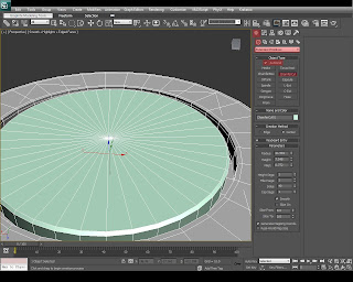
Step 29: With the Chamfer Cylinder selected go to Modify Tab and change the values as following: Height Segs 3, Fillet Segs 3, Sides 80 and Cap Segs 2. Also make sure that the height of the Cylinder is about 7 units.
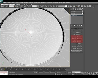
Step 30: Select the Bullet Shell and go to Modify Tab and apply a Shell modifier from the list.
(the shell is giving width to the lathe geometry)
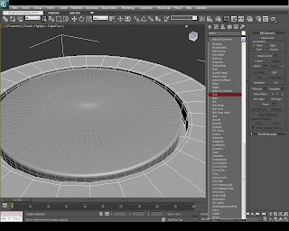
Step 31: We don't want our Bullet Shell to be too thick so change the Outer Ammount in the Shell modifier to 0.4.
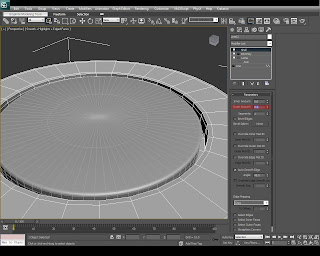
Step 32: On top of this apply a Turbosmooth modifier with an iteration value of 1.
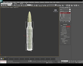
Step 33: For the actual bullet we need to make some small changes. Select the bullet go into the Modifier tab - Lathe and change the segments to 46 to have a smoother geometry.
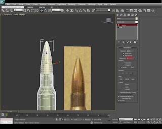
And that's it, your 3D bullet is done!
I hope you learned something from this tutorial.
If you have any question about this tutorial please post it in the comment section. I'll see you next time with another tutorial. Bye-bye :)
